


This article explores the concept of harmonic current emission (HCE), its classification under international standards, the impact of harmonics on power systems, standard testing methods, and common techniques used to mitigate harmonic currents.
Definition
In an ideal AC system, the current is a pure 50/60 Hz sinusoid. However, non-linear loads such as switched-mode power supply (SMPS) and LED drivers draw pulsed currents, which generate harmonics—multiples of the fundamental frequency—that can distort the waveform and degrade power quality.
Standards & Test Methods
The principal regulatory framework is IEC/EN 61000-3-2, which limits line current harmonics for equipment less than 16A per phase. It defines four mutually exclusive classes:
| Class | Typical Equipment | Limit Philosophy |
| A | Balanced three-phase loads, household appliances, audio gear | Fixed absolute current limits (e.g., 3rd ≤ 2.3 A, 5th ≤ 1.14 A) |
| B | Portable tools, non-professional welders | Limits of Class A × 1.5 |
| C | Lighting equipment > 25 W | Limits expressed as % of fundamental current (e.g., 3rd ≤ 30 λ %) |
| D | IT/AV equipment 75-600 W with “special wave-shape” | Power-related limits in mA/W (e.g., 3rd ≤ 3.4 mA/W, capped by Class A ceiling) |
For the currents which are above 16 A, IEC 61000‑3‑12/‑3‑4 apply to higher-power equipment. See the flowchart on page 3.
IEC 61000‑3‑2 requires a low-impedance AC source with tight voltage/frequency tolerance and low distortion. Current is measured using a FFT analyzer per IEC 61000‑4‑7, with a 10-cycle window resolving up to the 40th harmonic. THD and individual harmonics are recorded and automatically checked against class limits.
Why Harmonics Matter
Excess harmonic current results in increased losses and overheating due to skin effect and eddy currents, elevating conductor and transformer temperatures. It causes voltage distortion as upstream impedance turns distorted current into distorted voltage, impacting all connected equipment. Harmonics also reduce power factor by increasing reactive and non-fundamental components, while triplet harmonics (3rd, 9th, 15th) accumulate in the neutral of three-phase, four-wire systems, risking overload. These combined effects can shorten equipment lifespan and trigger nuisance tripping or utility penalties.
To Reduce Harmonics
- Passive Filtering / Passive PFC: Series chokes, or L‑C networks raise impedance for higher‑order components, smoothing the current. Advantage: simplicity; downside: bulky magnetics and limited efficacy over wide input range.
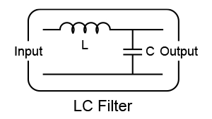
Fig. 1: LC Filter
- Active Power Factor Correction (PFC): Boost type converters synthesize a near sinusoidal input current in phase with the voltage, driving THD < 5 % and PF ≈ 1. Cost and switching losses are higher but performance is superior.
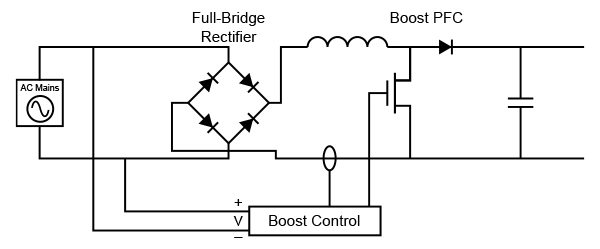
Fig. 2: PFC Converter
Delta’s Solution
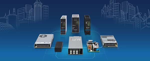
Delta provides power supplies in multiple form factors with compliance to EN 61000-3-2 harmonic current emission standards. The Force-GT Series (e.g., DRF-48V960W3GBA) in DIN rail format and the PJH Series (e.g., PJH-24V300WBCA) in open-frame design are both compliant with Class A, making them suitable for industrial applications such as automation systems, machinery, and control cabinets. The PMR Series (e.g., PMR-24V320W1AT), a panel mount model, meets both Class A and Class D requirements, allowing usage in diverse environments including IT, AV equipment, and display systems where Class D compliance is often required. This range allows Delta to support different installation needs while maintaining low harmonic emissions and regulatory compliance. The availability of Class A and Class D models across different designs provides flexibility for system designers and end-users.
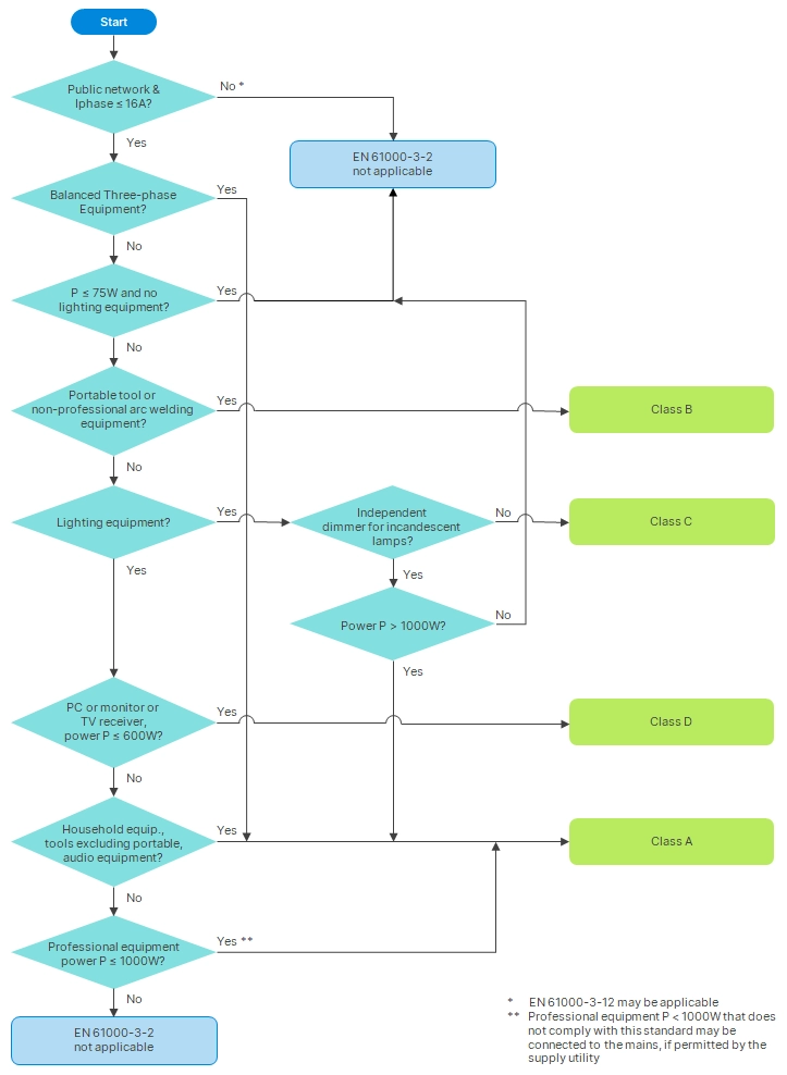
Fig. 3: Flow Chart of Harmonic Class Selection